NORDTEK DANMARK - DP - Compact Power Chokes, Low price - DPO, DPC, DPB, DPV, DPF. - servicekontoret.dk
DP - Compact Power Chokes, Low price - DPO, DPC, DPB, DPV, DPF.
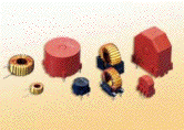
DP Series Power inductors provide an excellent, low cost alternative to conventional chokes or inductors. Used in EMI filtering and energy storage, these compact, low radiation inductors are extremely effective in controlling AC output ripple of Switch Mode Power Supplies.
Features
|
 |
Applications
- Switching Power Supplies
- EMI/RFI filtering
- Output Chokes
| IDC: 0.5A | IDC: 1A | IDC: 2A | IDC: 3A | IDC: 5A | IDC: 7.5A | IDC: 10A | IDC: 15 |
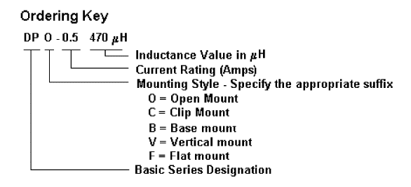
Ordering Key
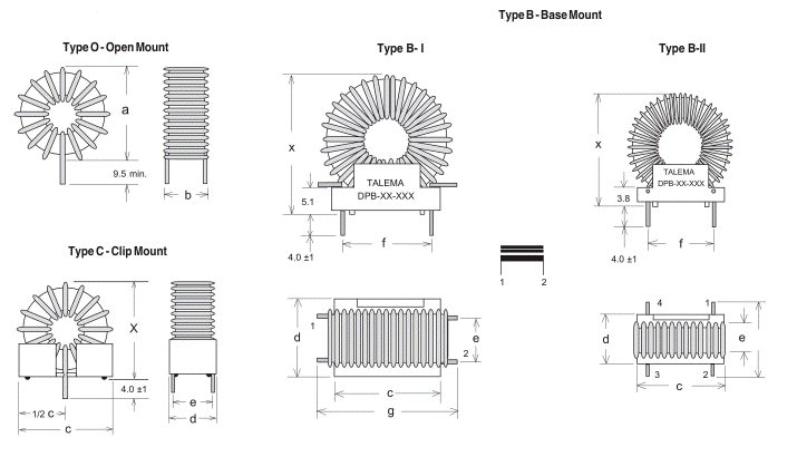
Mechanical Outlines & Dimensions
General Specifications
| Part Number | IDC (Amps) | L (µH) Typ. @ Rated Current |
Lo (µH) ±15% No Load |
DCR (Ohms) Max. |
Min. Energy Storage (µJ)* |
Wire Ø (mm) |
Coil Size mm O.D. x Ht. |
Mounting Style Availability / Size |
|||
| C | B | V | F | ||||||||
| DP_-0.5-47 DP_-0.5-68 DP_-0.5-100 DP_-0.5-150 |
0.5 | 47 68 100 150 |
50 73 109 167 |
0.095 0.115 0.140 0.173 |
5.9 8.5 12.5 18.8 |
0.400 0.400 0.400 0.400 |
14 x 8 14 x 8 14 x 8 15 x 8 |
2 2 2 2 |
3 3 3 3 |
2 2 2 2 |
2 2 2 2 |
| DP_-0.5-220 DP_-0.5-330 DP_-0.5-470 DP_-0.5-680 DP_-0.5-1000 |
220 330 470 680 1,000 |
258 393 557 849 1,358 |
0.215 0.265 0.322 0.398 0.503 |
27.5 41.3 58.8 85 125 |
0.400 0.400 0.400 0.400 0.400 |
15 x 9 15 x 9 20 x 9 20 x 10 21 x 11 |
2 2 3 3 3 |
3 3 3 3 5 |
2 2 3 3 4 |
2 2 3 3 3 |
|
| DP_-0.5-1500 DP_-0.5-2200 DP_-0.5-3300 DP_-0.5-4700 |
1,500 2,200 3,300 4,700 |
1,863 3,131 5,024 6,287 |
0.714 0.926 1.173 1.421 |
188 275 413 588 |
0.400 0.400 0.400 0.400 |
25 x 12 25 x 12 26 x 13 32 x 15 |
5 5 5 5 |
5 5 5 8 |
4 4 5 5 |
4 4 6 6 |
|
Top of page
| Part Number | IDC (Amps) | L (µH) Typ. @ Rated Current |
Lo (µH) ±15% No Load |
DCR (Ohms) Max. |
Min. Energy Storage (µJ)* |
Wire Ø (mm) |
Coil Size mm O.D. x Ht. |
Mounting Style Availability / Size |
|||
| C | B | V | F | ||||||||
| DP_-1.0-22 DP_-1.0-33 DP_-1.0-47 DP_-1.0-68 DP_-1.0-100 |
1.0 | 22 33 47 68 100 |
23 37 53 80 127 |
0.041 0.052 0.063 0.077 0.097 |
11.0 16.5 23.5 34 50 |
0.500 0.500 0.500 0.500 0.500 |
14 x 8 14 x 8 14 x 8 14 x 8 15 x 8 |
2 2 2 2 2 |
3 3 3 3 3 |
2 2 2 2 2 |
2 2 2 2 2 |
| DP_-1.0-150 DP_-1.0-220 DP_-1.0-330 DP_-1.0-470 |
150 220 330 470 |
207 345 491 601 |
0.123 0.196 0.193 0.180 |
75 110 165 235 |
0.500 0.450 0.500 0.600 |
15 x 9 15 x 9 20 x 9 27 x 12 |
2 2 3 5 |
3 3 3 5 |
3 3 3 5 |
2 2 3 6 |
|
| DP_-1.0-680 DP_-1.0-1000 DP_-1.0-1500 DP_-1.0-2200 DP_-1.0-3300 |
680 1,000 1,500 2,200 3,300 |
891 1,619 2,149 3,609 4,731 |
0.220 0.426 0.532 0.689 0.609 |
340 500 750 1,100 1,650 |
0.600 0.500 0.500 0.500 0.600 |
27 x 13 26 x 13 30 x 14 31 x 15 43 x 15 |
5 4 5 5 - |
5 5 5 5 8 |
5 5 5 6 - |
6 6 6 6 - |
|
Top of page
| Part Number | IDC (Amps) | L (µH) Typ. @ Rated Current |
Lo (µH) ±15% No Load |
DCR (Ohms) Max. |
Min. Energy Storage (µJ)* |
Wire Ø (mm) |
Coil Size mm O.D. x Ht. |
Mounting Style Availability / Size |
|||
| C | B | V | F | ||||||||
| DP_-2.0-22 DP_-2.0-33 DP_-2.0-47 DP_-2.0-68 |
2.0 | 22 33 47 68 |
27 45 73 109 |
0,070 0,089 0,090 0,089 |
44 66 94 136 |
0,400 0,400 0,450 0,500 |
14 x 8 14 x 8 15 x 8 15 x 8 |
2 2 2 2 |
3 3 3 3 |
2 2 2 2 |
2 2 2 2 |
| DP_-2.0-100 DP_-2.0-150 DP_-2.0-220 DP_-2.0-330 DP_-2.0-470 |
100 150 220 330 470 |
157 207 328 575 720 |
0,109 0,106 0,153 0,202 0,214 |
200 300 440 660 940 |
0,500 0,600 0,560 0,560 0,600 |
15 x 9 25 x 12 25 x 11 26 x 12 30 x 14 |
3 4 4 4 5 |
3 5 5 5 5 |
3 4 4 4 5 |
3 4 4 4 6 |
|
| DP_-2.0-680 DP_-2.0-1000 DP_-2.0-1500 DP_-2.0-2200 |
680 1.000 1.500 2.200 |
1.251 1.429 2.488 3.218 |
0,282 0,335 0,441 0,405 |
1.360 2.000 3.000 4.400 |
0,600 0,600 0,600 0,710 |
30 x 14 42 x 14 42 x 15 51 x 22 |
5 - - - |
5 5 8 10 |
5 9 9 - |
6 - - - |
|
Top of page
| Part Number | IDC (Amps) | L (µH) Typ. @ Rated Current |
Lo (µH) ±15% No Load |
DCR (Ohms) Max. |
Min. Energy Storage (µJ)* |
Wire Ø (mm) |
Coil Size mm O.D. x Ht. |
Mounting Style Availability / Size |
|||
| C | B | V | F | ||||||||
| DP_-3.0-15 DP_-3.0-22 DP_-3.0-33 DP_-3.0-47 DP_-3.0-68 |
3.0 | 15 22 33 47 68 |
21 34 49 75 92 |
0.039 0.038 0.038 0.048 0.060 |
68 99 149 212 306 |
0.500 0.500 0.630 0.630 0.710 |
14 x 8 14 x 8 19 x 8 20 x 8 25 x 12 |
2 2 3 3 4 |
3 3 3 3 5 |
2 2 3 3 4 |
2 2 3 3 4 |
| DP_-3.0-100 DP_-3.0-150 DP_-3.0-220 DP_-3.0-330 |
100 150 220 330 |
157 207 346 625 |
0.080 0.107 0.134 0.142 |
458 675 990 1,485 |
0.710 0.710 0.630 0.710 |
25 x 12 25 x 12 29 x 13 30 x 14 |
4 4 5 5 |
5 5 5 5 |
4 4 5 5 |
4 4 6 6 |
|
| DP_-3.0-470 DP_-3.0-680 DP_-3.0-1000 DP_-3.0-1500 DP_-3.0-2200 |
470 680 1,000 1,500 2,200 |
727 1,124 1,493 2,324 4,090 |
0.187 0.302 0.304 0.384 0.509 |
2,115 3,060 4,500 6,750 9,900 |
0.670 0.630 0.670 0.670 0.670 |
42 x 14 42 x 16 49 x 20 53 x 24 54 x 26 |
- - - - - |
5 8 10 11 11 |
9 - - - - |
- - - - - |
|
Top of page
| Part Number | IDC (Amps) | L (µH) Typ. @ Rated Current |
Lo (µH) ±15% No Load |
DCR (Ohms) Max. |
Min. Energy Storage (µJ)* |
Wire Ø (mm) |
Coil Size mm O.D. x Ht. |
Mounting Style Availability / Size |
|||
| C | B | V | F | ||||||||
| DP_-5.0-15 DP_-5.0-22 DP_-5.0-33 DP_-5.0-47 |
5.0 | 15 22 33 47 |
23 28 48 82 |
0.029 0.039 0.036 0.043 |
188 275 413 588 |
0.600 0.600 0.710 0.750 |
20 x 8 25 x 12 25 x 12 25 x 12 |
3 4 4 4 |
3 5 5 5 |
3 4 4 4 |
3 4 4 4 |
| DP_-5.0-68 DP_-5.0-100 DP_-5.0-150 DP_-5.0-220 |
68 100 150 220 |
137 172 221 381 |
0.055 0.059 0.094 0.097 |
850 1,250 1,875 2,750 |
0.750 0.800 0.710 0.800 |
26 x 12 30 x 13 41 x 13 41 x 13 |
4 5 - - |
5 5 5 5 |
4 5 9 9 |
4 5 - - |
|
| DP_-5.0-330 DP_-5.0-470 DP_-5.0-680 DP_-5.0-1000 |
330 470 680 1,000 |
475 852 1,186 2,093 |
0.156 0.187 0.196 0.206 |
4,125 5,875 8,500 12,500 |
0.710 0.750 0.800 0.900 |
49 x 20 49 x 20 53 x 25 55 x 26 |
- - - - |
10 10 11 11 |
- - - - |
- - - - |
|
Top of page
| Part Number | IDC (Amps) | L (µH) Typ. @ Rated Current |
Lo (µH) ±15% No Load |
DCR (Ohms) Max. |
Min. Energy Storage (µJ)* |
Wire Ø (mm) |
Coil Size mm O.D. x Ht. |
Mounting Style Availability / Size |
|||
| C | B | V | F | ||||||||
| DP_-7.5-15 DP_-7.5-22 DP_-7.5-33 DP_-7.5-47 DP_-7.5-68 |
7.5 | 15 22 33 47 68 |
18 30 49 84 105 |
0.022 0.025 0.025 0.026 0.040 |
422 619 928 1,322 1,913 |
0.750 0.800 0.900 0.950 0.900 |
30 x 14 30 x 14 30 x 14 31 x 14 42 x 14 |
5 5 5 5 - |
5 5 5 5 5 |
5 5 5 5 9 |
6 6 6 6 - |
| DP_-7.5-100 DP_-7.5-150 DP_-7.5-220 DP_-7.5-330 DP_-7.5-470 |
100 150 220 330 470 |
160 219 373 605 1,054 |
0.045 0.074 0.070 0.090 0.085 |
2,813 4,219 6,188 9,281 13,219 |
1.000 0.850 1.000 1.000 1.180 |
43 x 17 50 x 21 51 x 22 54 x 25 55 x 28 |
- - - - - |
8 10 10 11 11 |
- - - - - |
- - - - - |
|
Top of page
| Part Number | IDC (Amps) | L (µH) Typ. @ Rated Current |
Lo (µH) ±15% No Load |
DCR (Ohms) Max. |
Min. Energy Storage (µJ)* |
Wire Ø (mm) |
Coil Size mm O.D. x Ht. |
Mounting Style Availability / Size |
|||
| C | B | V | F | ||||||||
| DP_-10-15 DP_-10-22 DP_-10-33 DP_-10-47 |
10 | 15 22 33 47 |
21 28 46 75 |
0.013 0.021 0.022 0.028 |
750 1,100 1,650 2,350 |
0.950 0.900 1.000 1.000 |
30 x 14 41 x 14 42 x 14 42 x 14 |
5 - - - |
5 5 5 5 |
5 9 9 9 |
6 - - - |
| DP_-10-68 DP_-10-100 DP_-10-150 DP_-10-220 |
68 100 150 220 |
89 152 248 427 |
0.042 0.044 0.041 0.054 |
3,400 5,000 7,500 11,000 |
0.900 1.000 1.180 1.180 |
50 x 21 50 x 21 55 x 26 55 x 26 |
- - - - |
10 10 11 11 |
- - - - |
- - - - |
|
Top of page
| Part Number | IDC (Amps) | L (µH) Typ. @ Rated Current |
Lo (µH) ±15% No Load |
DCR (Ohms) Max. |
Min. Energy Storage (µJ)* |
Wire Ø (mm) |
Coil Size mm O.D. x Ht. |
Mounting Style Availability / Size |
|||
| C | B | V | F | ||||||||
| DP_-15-6.8 DP_-15-10 DP_-15-15 DP_-15-22 |
15 | 6.8 10 15 22 |
8 14 22 36 |
0.009 0.012 0.011 0.014 |
765 1,125 1,688 2,475 |
1.000 1.000 1.180 1.250 |
41 x 14 41 x 14 41 x 14 44 x 18 |
- - - - |
5 5 5 8 |
9 9 9 - |
- - - - |
| DP_-15-33 DP_-15-47 DP_-15-68 DP_-15-100 |
33 47 68 100 |
49 75 123 207 |
0.018 0.016 0.018 0.023 |
3,713 5,288 7,650 11,250 |
1.180 1.400 1.500 1.500 |
50 x 21 51 x 22 52 x 23 56 x 27 |
- - - - |
10 11 11 11 |
- - - - |
- - - - |
|
Notes:
- The µJoule rating (0.5 x LI2) is the ability of the inductor to store energy
- Inductance is measure at 0.10Vrms @ 10kHz without DC Current and 0.25Vrms @ 10kHz with DC Current.

Top of page
Mechanical Outlines & Dimensions

 |
|
||||||||||||||||||||||||||||||||||||||||||||||||||||||||||||||||||||||||||||||||||||||||||||||||||||||||||||||||
Top of page


